3.1 Modifying boards.txt
We begin by creating an entry for the OWHL’s hardware configuration. This is accomplished by modifying a file used by the Arduino software, boards.txt, which lists the configurations for the various Arduino boards.
Windows
- On a Windows installation, the file can be found in the Arduino installation folder (typicallyPrograms (x86)/Arduino/).
- Navigate to hardware/arduino/avr/ to find boards.txt.
Mac OSX
- On a Mac OSX installation, open a Finder window and navigate to Applications > Arduino thenlong-click and choose “Show Package Contents”.
- Then navigate to Contents/Resources/Java/hardware/Arduino/avr to find boards.txt.The boards.txt file can be opened in a basic text editor (Notepad, TextEdit, etc.), and the following code (between the lines of ####) can be copied and pasted into boards.txt:
################################################################
# For Arduino IDE v 1.6.3 or later
# Tested successfully using Arduino as ISP programmer to burn
# bootloader on OWHL.
# Cut and paste this entry into your existing boards.txt file # found inside the /hardware/arduino/avr/ directory.
# Select the OWHL (8MHz internal clock) entry in the
# Arduino IDE menu under Tools>Board>
OWHLatmega328.name=OWHL (8 MHz internal clock) OWHLatmega328.upload.tool=arduino:avrdude OWHLatmega328.upload.protocol=arduino OWHLatmega328.upload.maximum_size=30720 OWHLatmega328.upload.speed=57600
OWHLatmega328.bootloader.low_fuses=0xE2 OWHLatmega328.bootloader.high_fuses=0xDA OWHLatmega328.bootloader.extended_fuses=0x05
OWHLatmega328.bootloader.file=atmega/ATmegaBOOT_168_atmega328_pro_8MHz.hex OWHLatmega328.bootloader.unlock_bits=0x3F OWHLatmega328.bootloader.lock_bits=0x0F OWHLatmega328.bootloader.tool=arduino:avrdude OWHLatmega328.build.mcu=atmega328p
OWHLatmega328.build.f_cpu=8000000L OWHLatmega328.build.core=arduino OWHLatmega328.build.variant=standard
#############################################################
After adding that code to the boards.txt file, and restarting the Arduino software, you should find an entry for “OWHL (8 MHz internal clock)” under the Tools>Board menu. Choose that entry when you burn the bootloader.
3.2 Burning the Bootloader
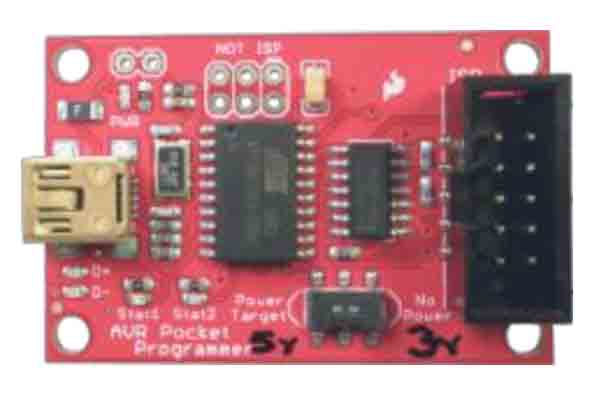
A brand new ATmega328p chip needs to have a small program (a bootloader) installed on the chip using an In-System Programmer (ISP) initially so that it can then be programmed and communicated with using a standard USB to Serial converter in later steps. There are several commercial ISPs available for Arduinos (Figure 7) but a standard Arduino Uno can also be used as an ISP. The instructions below outline the use of an Arduino Uno as an ISP.
These steps are based on the instructions on this page: http://www.arduino.cc/en/Tutorial/ArduinoISP
- Open Arduino and set Tools>Board to Arduino Uno (this is the board you will use as the
programmer).
- Upload the Example>ArduinoISP sketch to the Arduino Uno. The Uno is now programmed to
behave as a programmer for new AVR chips (this is completely reversible).
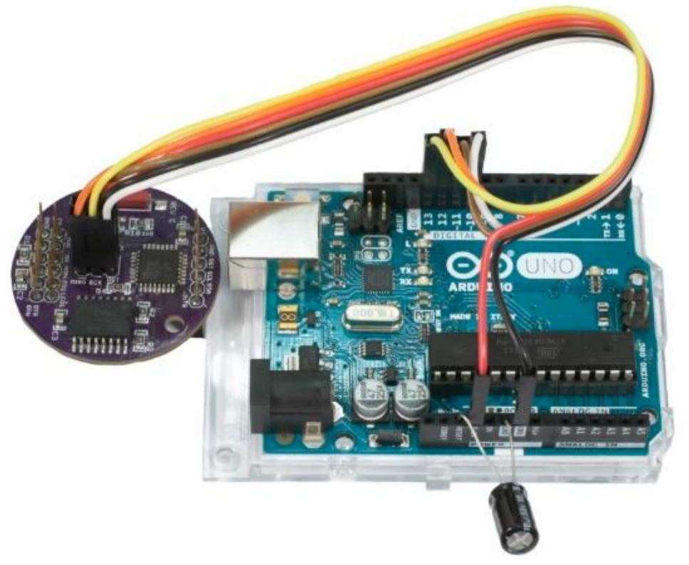
- Place a 10μF capacitor between Reset and Ground on the Arduino Uno, with the negative leg in
the Ground header.
- Change the Arduino Tools>Board to “OWHL (8 MHz internal clock)”
- Power down the Uno, and connect the ISP header on the OWHL to the appropriate pins on the
Uno. The pin layout on the OWHL is shown in (Figure 8)

- Pin connections between the OWHL and Arduino Uno to allow the use of the Arduino Uno As ISP functionality:
- OWHL Pin 1 MISO to Uno digital pin 12 o OWHLPin2+VcctoUno3V3pin
- OWHL Pin 3 SCK to Uno digital pin 13 o OWHL Pin 4 MOSI to Uno digital pin 11 o OWHL Pin 5 Reset to Uno digital pin 10 o OWHLPin6GNDtoUnoGNDpin
- To be clear, the OWHL is the “slave” in this scenario, and the Arduino Uno is the “master” when burning the bootloader.
- Plug the USB cable back into the Uno programmer board.
- Go to Tools>Programmer and choose “Arduino as ISP”. If you are using a commercial ISP board instead, choose the Programmer option appropriate for your programmer.
- Go to Tools>Burn Bootloader and watch the bootloader burn happen over a few minutes.
With a bootloader program installed on the OWHL, the ISP can be disconnected. The ISP should not be needed again for the OWHL.
3.3 Connecting the USB to Serial Adapter
After the bootloader has been burned onto a new OWHL, all further programming can use a USB to Serial adapter, also commonly called an FTDI adapter (FTDI is a manufacturer of electronic parts). These USB to Serial adapters can be sourced from several vendors, such as the Adafruit FTDI Friend or Sparkfun FTDI Basic (Figure 10).
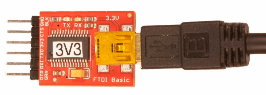
Figure 10: FTDI Basic adapter from Sparkfun.com, 3.3 volt model. A set of 6 pins (shown) is useful for attaching the FTDI Basic to the female FTDI header on the bottom of the CPU circuit board or Power circuit board.
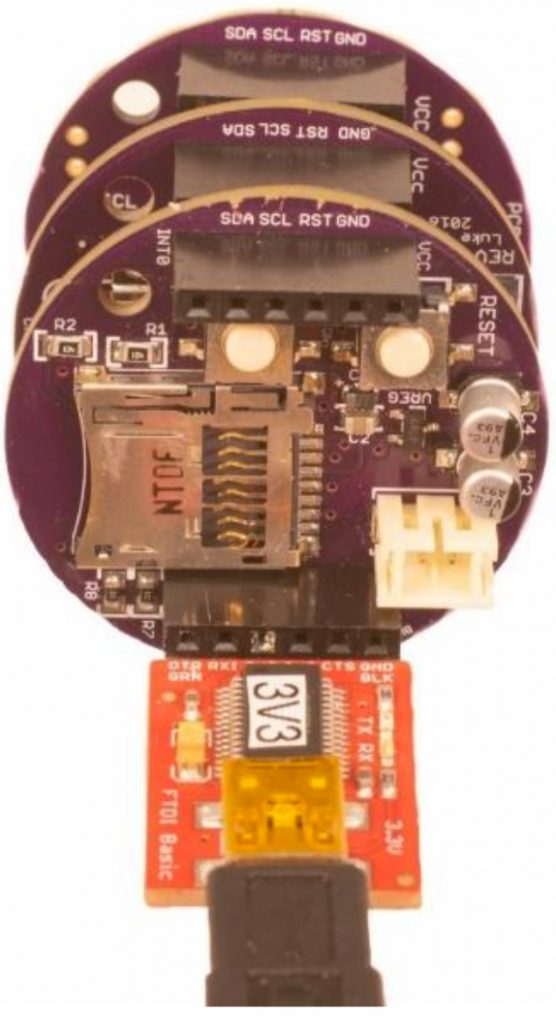
The FTDI adapter can be connected to the 1×6 FTDI header, which is the outer header of the two rows of 1×6 headers found on the OWHL circuit boards. Each of the OWHL circuit boards has the FTDI header pins, so you can connect the FTDI adapter to either the CPU board directly, or the Power board when the CPU board is already attached to the Power board (this would be the normal arrangement when an OWHL is fully assembled).
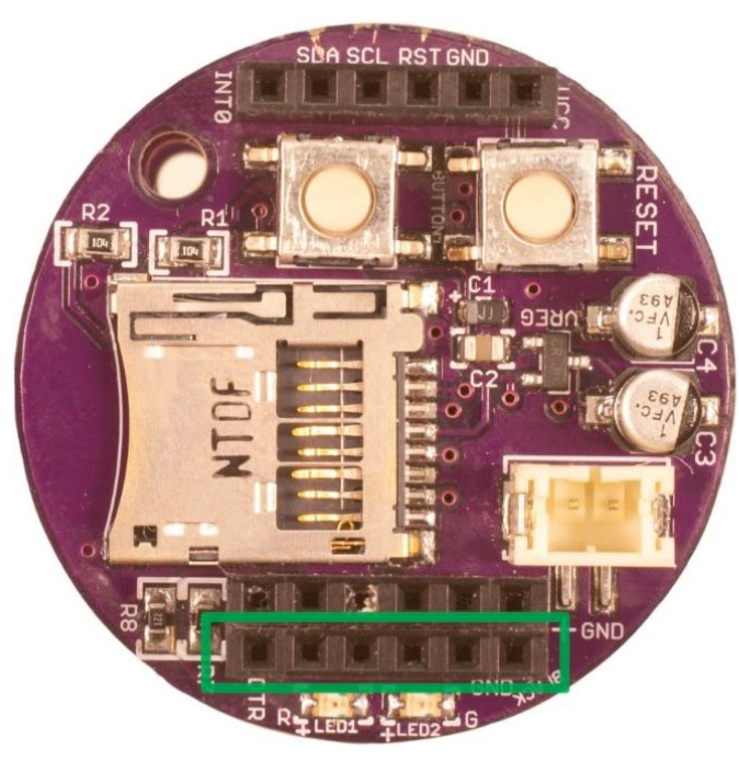
The orientation of the FTDI adapter matters, and could be easily hooked up backward, so pay careful attention when connecting the FTDI adapter to the OWHL. One end of the 1×6 FTDI header on the OWHL boards is labeled “black” and “GND”, and the opposite end is labeled “green” and “DTR” (Figure 11). These labels correspond to the labels commonly used on various FTDI adapters and should be matched up when connecting the FTDI adapter to the OWHL header (Figure 12).
3.4 Setting the Real Time Clock
With the USB to Serial adapter (FTDI adapter) connected and the FTDI port selected in the Arduino software, the OWHL will be powered up and ready to program using the Arduino software.
The first task will be to program the real-time clock (RTC), which should already have its CR1220 battery installed.
- In Arduino, go to File>Sketchbook>OWHL>settime_Serial
- The settime_Serial.ino program window will open in Arduino
- Click the button at the top of the Arduino window that looks like a right arrow “Upload”, or go to Sketch>Upload
- The Arduino software will attempt to program
the OWHL. You should see a notification in the lower section of the Arduino window telling you when the program is successfully uploaded. - After a successful upload, open the Arduino Serial Monitor window, using the magnifying glass icon in the upper right of the window, or using the menu Tools>Serial Monitor
- In the Serial Monitor window at the bottom, you will find a menu item for the serial communications speed, which is typically set to “115200 baud” by default. Set this menu to “57600 baud” to communicate with the OWHL.
- The Serial Monitor should show a message prompting you to enter the date and time in the format YYYY MM DD HH MM SS
- The date and time can be typed in the text entry field at the top of the Serial Monitor window
- Follow the format exactly, including the spaces between values
- For example, if you want to set the clock to read 3:20:30 PM on January 6, 2019, youwould type the values 2019 01 06 15 20 30
- Choose a time value in seconds that is slightly ahead of the current time as you type in the values
- When you have finished entering the date and time, wait until your clock time matches the value you entered, and hit the Return key to send the time value to the OWHL
- After a successful time upload, the Serial Monitor should start showing you the OWHL’s current time.
- If you missed setting the correct value, you can retry as many times as you like by entering a new time in the Serial Monitor and hitting Return when that time ticks over.
- We strongly recommend always programming the OWHL clock in the UTC zone (also known as Greenwich Mean Time). This is a standard for most data collecting instruments and avoids any ambiguity about time zones or Daylight Savings Time changes. The OWHL is not capable of observing Daylight Savings Time.
To check that the Real Time Clock successfully keeps time on its own without external power, close the Serial Monitor and unplug the OWHL from the FTDI adapter. The OWHL will power down at this point, but the CR1220 backup battery on the Real Time Clock should keep the clock running. Plug the FTDI adapter back into the OWHL and open the Serial Monitor. The current date and time should be displayed on the serial monitor.
3.5 Programming a Serial Number Onto the OWHL
In cases where you will have multiple OWHL devices, it is desirable to make sure each OWHL imprints a unique serial number in the header of each output .csv file. To program a serial number, we use the serial_number_generator.ino program found in the Arduino File>Sketchbook>OWHL menu.
- Connect the FTDI adapter to the OWHL, and plug in the FTDI USB cable to the computer
- Bring the serial_number_generator.ino program window to the front
- Click on the Upload button (right arrow) found at the top of the Arduino window, or go to
Sketch>Upload
- The upload status should be shown in the lower portion of the Arduino window
- The serial number generator program will write a serial number based on the upload date and
time (for example SN20190612093030 if it was programmed on June 12, 2019 at 9:30:30AM) to a portion of the OWHL’s memory called EEPROM memory. This memory is not normally accessed during OWHL operation and will retain the serial number even as you upload other programs to the OWHL
- If you open the Serial Monitor window, the programmed serial number should be displayed.
3.6 Programming the Main OWHL Data Collection Program
After the Real Time Clock has been set, and a serial number has been programmed, you can upload the main OWHL data collection program, which is the file OWHL.ino.
- Connect the FTDI adapter to the OWHL and plug the USB cable into the computer
- Open Arduino, and go to File>Sketchbook>OWHL>OWHL
- The OWHL.ino program should open
- Click the Upload icon (right arrow) at the upper left of the Arduino window, or go to Sketch>Upload
- The upload progress will be shown in the lower portion of the Arduino window
- After a successful upload, the OWHL should play a little chime to indicate that it is starting data collection. If there are errors during startup, including a bad date and time value or missing micro SD card, the red and green LEDs will flash and an annoying beep will sound.
- While the FTDI adapter is connected to the OWHL, the Serial Monitor window in Arduino can be opened to show the status of the OWHL.
- Now the OWHL will begin collecting data any time power is applied and will continue collecting data until power is disconnected.
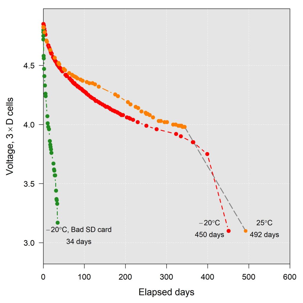
Figure 13: Example battery voltage depletion trends for three OWHL test units in the laboratory. All three devices were powered with 3 x “D” cell alkaline batteries, with an initial combined voltage of ~4.8V. The left most (green) curve illustrates the effect of using a microSD card that is not power efficient, while the two curves on the right used modern name brand SanDisk 16 GB cards purchased in 2014.
3.7 Choosing a MicroSD Card
One of the main sources of power consumption in the OWHL is the microSD card, and identifying a power-efficient card can be important for getting the longest run time out of a set of batteries. As the drive to improve the battery life of consumer electronics has progressed, microSD cards have generally become more power efficient, and this is accomplished by having the card quickly go into a low power “sleep” state when it is not being actively accessed. Testing the power draw of an SD card, described below, is somewhat advanced or time consuming, so we will note that we have had good luck with name brand cards in the 4 to 32 GByte capacity range from major memory suppliers such as SanDisk, Kingston, and Samsung. The relatively simple electronics of the OWHL cannot use the extra features of extremely fast or high capacity microSD cards, so there is no advantage to buying more expensive cards advertised as being high performance. For those that want to estimate the efficiency of their cards, we detail two approaches we have used for monitoring power consumption.
3.8 Monitoring Battery Voltage
The simplest option for monitoring battery power usage, but also the most time-consuming, is to assemble a fully-programmed OWHL unit with a microSD card, attach a battery, and monitor the battery voltage over weeks or months. Using a handheld multimeter, measure the initial battery voltage at the start of the trial. A set of 3 new 1.5V alkaline cells should have a combined voltage of approximately 4.8 to 5 V, as brand new cells will often measure around 1.6 to 1.65 V. Make repeated recordings of the battery voltage approximately weekly to establish the trend in battery power consumption.
Figure 13 shows three example battery voltage curves for OWHL test units powered off of 3 “D” cell batteries. The test unit with an inefficient older unbranded microSD card depleted the batteries from an initial 4.8 V down to 3.81 V after 17 days and had reached the 3.1 V cutoff by 34 days. In the same 17 day time span, the two test units using modern SanDisk 8GB Class 4 microSD card had only dropped to 4.62 V from an initial voltage of 4.8 V, and by 34 days had dropped to 4.5 V, and both units ultimately ran for more than year before hitting the 3.1 V cutoff. The rate of discharge would be steeper for smaller battery cell capacities such as “AA” or “AAA” sizes, so Figure 13 should not be used as a guide when using smaller battery sizes.
3.9 Monitoring Current Draw With an Oscilloscope
If you have access to an oscilloscope, it can be used to monitor the current draw of an assembled OWHL unit in real time. This method requires an oscilloscope, tools to cut, strip, and solder the wire used in the battery connector pigtail, and a 1 ohm axial resistor with a 1⁄4 watt or higher power rating (Figure 14A). Axial resistors are the old-style resistors with two wire leads sticking out of a central ceramic cylinder, often with colored bands on the cylinder.
- Cut the negative (ground, typically black color) wire of the battery pigtail near its midpoint.
- Strip back about 5-10 mm of insulation from each half of the cut wire.
- Solder the 1 ohm resistor between the two halves of the cut and stripped wire (Figure 14B).
- Attach the oscilloscope probe lead to the end of the 1 ohm resistor closest to the OWHL.
- Attach the oscilloscope ground lead (often the short alligator clip hanging off of the oscilloscope probe) to the end of the 1 ohm resistor closest to the battery pack (Figure 14C).
- Plug the battery pack into the OWHL and let the OWHL start recording data.
- On the oscilloscope, set the Volts/Division to 10 mV, and set the time base (horizontal axis) to a long interval such as 250 ms or as high as 1 second. Set the oscilloscope to free run.
- Alternatively, use the voltage trigger adjustment to set the trigger at a level about 15-20 mV above the baseline voltage reading seen on the oscilloscope screen while the system is running. This should catch and trigger on the high voltage peak that occurs at the start of a microSD card write event.
- While the oscilloscope is running, look for the occasional spike in the voltage trace, which indicates the increased current draw (converted to voltage by the oscilloscope and resistor) that occurs when the microSD card awakens and writes data to memory.
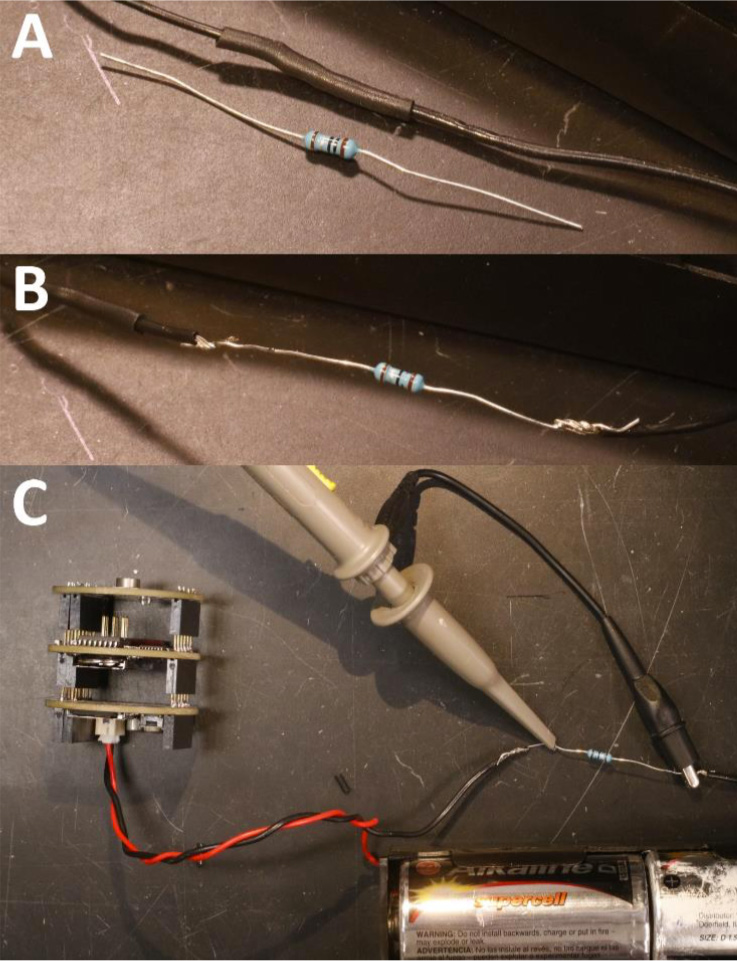
Figure 14: Inserting a 1 ohm resistor into the negative wire lead of the battery pack.
A) Resistor and negative wire.
B) The black wire is cut, stripped, and the 1 ohm resistor is soldered in place.
C) An oscilloscope lead and ground clip are attached to the two legs of the 1 ohm resistor, and the battery pack is plugged into an OWHL programmed with the main data collection firmware.
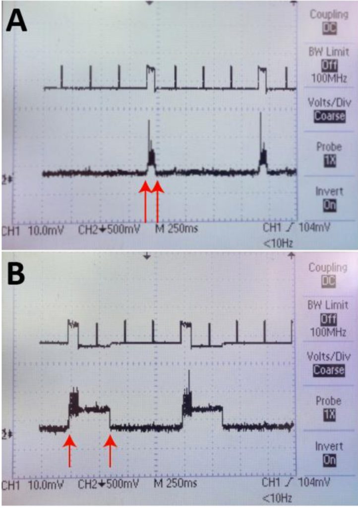
The panels in Figure 15 show a comparison of voltage traces from two different microSD cards mounted in an OWHL. The name brand (SanDisk, 16GB capacity) card shown in Figure 15A creates a voltage peak of approximately 60-75 ms duration during a write event, while the unbranded card used in Figure 15B creates a much longer duration voltage rise of around 300 ms during which the power consumption of the OWHL is substantially increased. The short duration rise of the SanDisk card will minimize the overall power consumption of the OWHL and give the longest run time.
Figure 15:
A) Voltage trace from an oscilloscope showing the rise in voltage measured across a 1 ohm resistor corresponding to the increased current draw during a microSD card write event. The red arrows mark the start and end of the write event, which lasts approximately 60-75 ms. The short duration of the peak for the microSD card write event illustrates that the card quickly returns to a low power sleep mode after the write event.
B) Voltage trace from a low quality microSD card showing a longer period of high voltage (marked by the red arrows), corresponding to high current draw during and after a write event. Here the voltage trace stays high for approximately 300 ms before reentering a low power state.