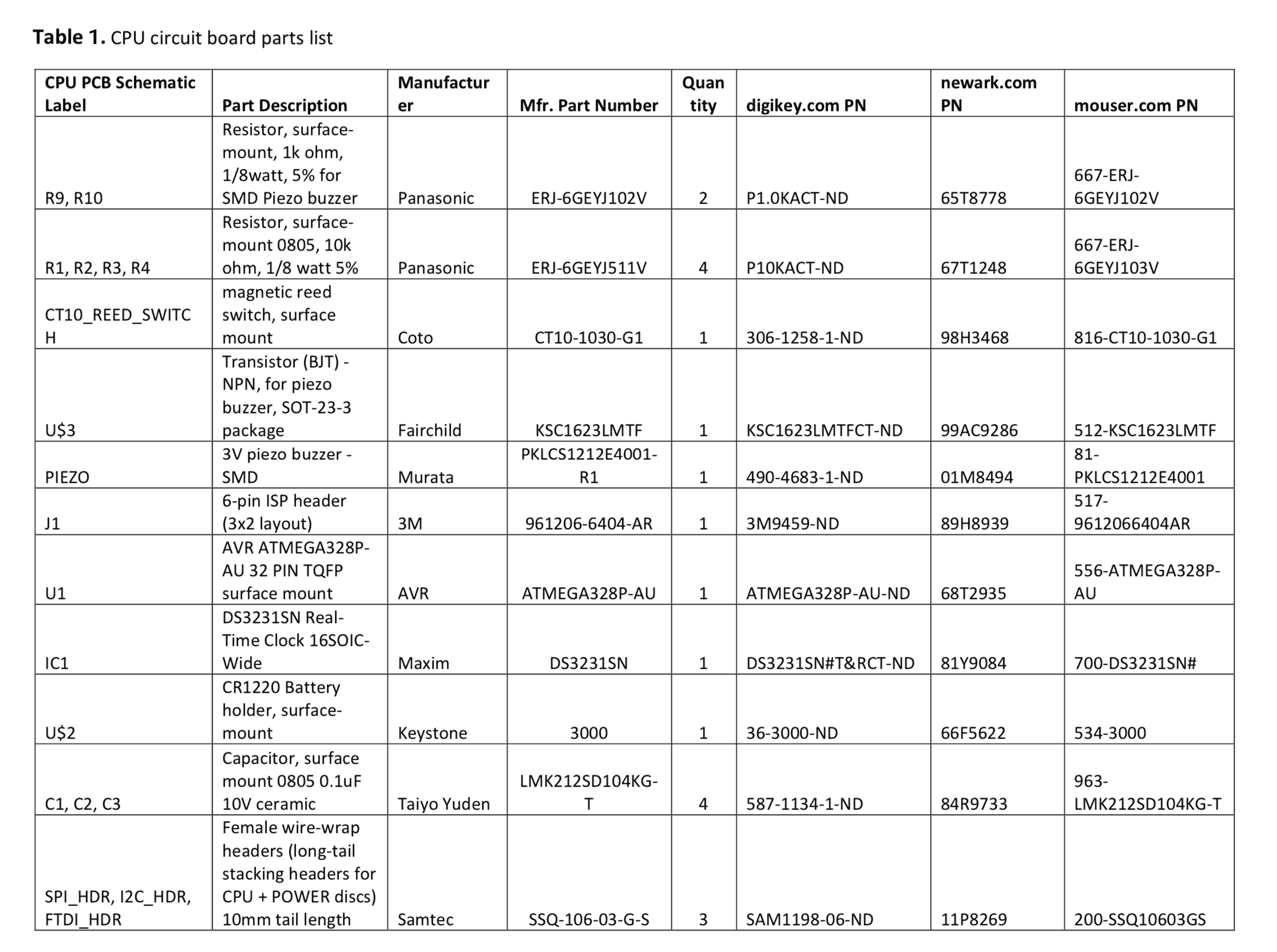
Soldering Iron (temperature adjustable solder workstation preferred)
Soldering Hot Air Re-work Station (optional)
SMD Reflow oven (optional)
Vise (to hold PCBs)
Tweezers (to apply SMD parts to PCBs)
Materials needed:
PCB Circuit Boards
Solder Paste
Rosin Core Solder (Lead-free preferred)
PCB Circuit Board Stencils (optional)
Plastic Scraper Card (optional)
For each PCB circuit board:
Carefully apply a tiny dot of solder paste to each pad that is labeled below OR
Order a solder paste stencil when ordering the PCB circuit boards
Using the solder paste stencil:
Position & align solder paste stencil carefully over the board pad locations
Apply solder paste to stencil
Drag a flat plastic card across the stencil holes to fill with solder paste (a credit card works well for this)
Clear excess paste from the stencil with the card
The boards need to have the solder paste reach a temperature of 235 deg C to allow the solder to flow across the pads, cool down, solidify and anchor the parts to the circuit boards. This can be done in several ways:
We used a reflow oven to complete the soldering process as it allows for making multiple boards at a time (preferred method)
Reflow ovens can be commercially purchased for ~$200 – $2000 (depending on size and wattage)
Use a solder paste stencil, or solder paste syringe, to apply solder paste to the solder pads on the top surface of the circuit board. Do not place solder on the through-hole pads, as these will be soldered separately.
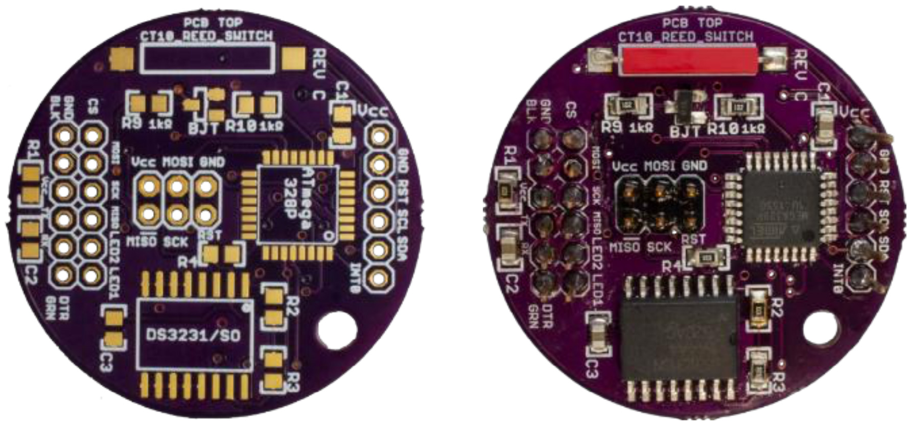
Place the ATmega328p (CPU PCB parts list U1). The top plastic surface of the chip has a circular depression in one corner, which marks the location of pin 1. Align this circle with the white circle on the circuit board.
Place resistors 10k ohm resistors (CPU PCB parts list R1, R2, R3, R4) on the marked footprints R1, R2, R3, R4 (orientation does not matter).
Place 1k ohm resistors (CPU PCB parts list R9, R10) on the marked footprints R9, R10 (orientation does not matter).
Place the DS3231 real-time clock chip (CPU PCB parts list IC1). The plastic top of the chip has a semi-circular notch at one end, marking where pins 1 and 16 are. The circuit board footprint has a white dot next to pin 1. Place the chip so that pin 1 (top left of the chip looking down from the top) aligns with the pad marked by the white dot on the board.
Place the BJT transistor (CPU PCB parts list U$3) on its footprint between resistors R9 and R10.
Place 0.1 μF capacitors (CPU PCB parts list C1, C2, C3) on footprints C1, C2, C3 (orientation does not matter).
Place the reed switch (CPU PCB parts list CT10_REED_SWITCH). Orientation does not matter.
Solder the surface mount components using a reflow solder oven or hot air reflow station.
Figure 2: Left: top surface of the bare CPU circuit board. Right: top surface of the circuit board with all parts soldered.
2.2 CPU Board Assembly Continued
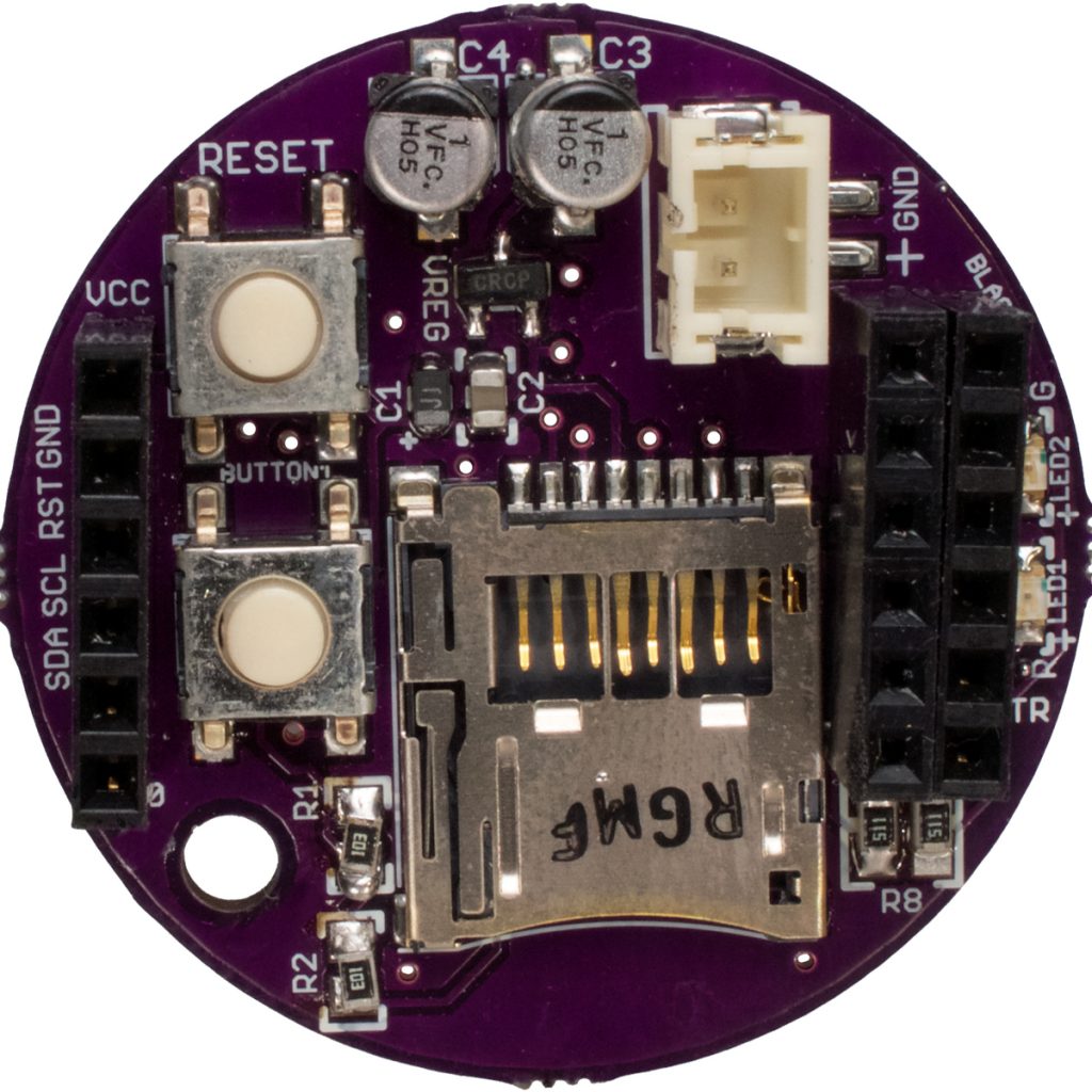
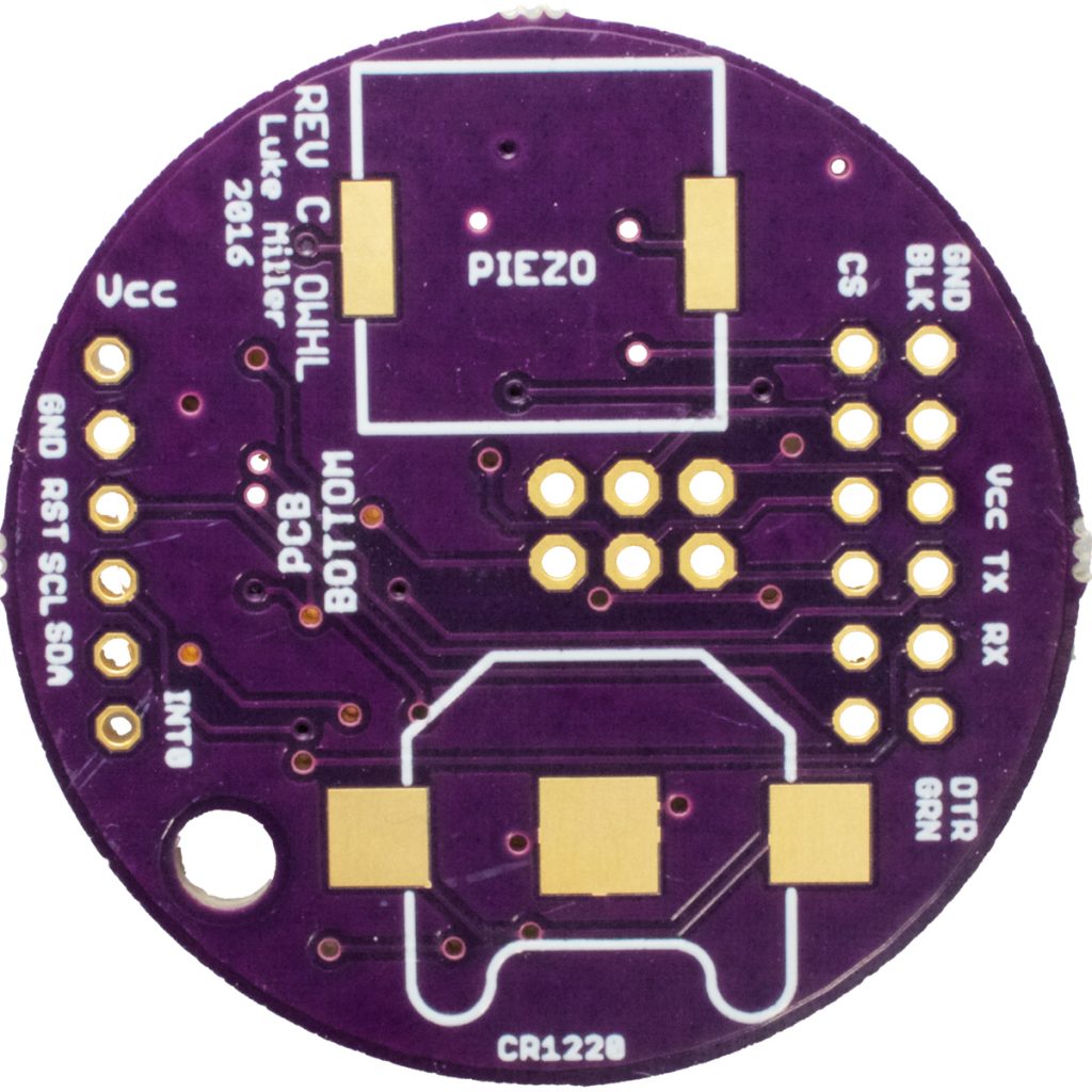
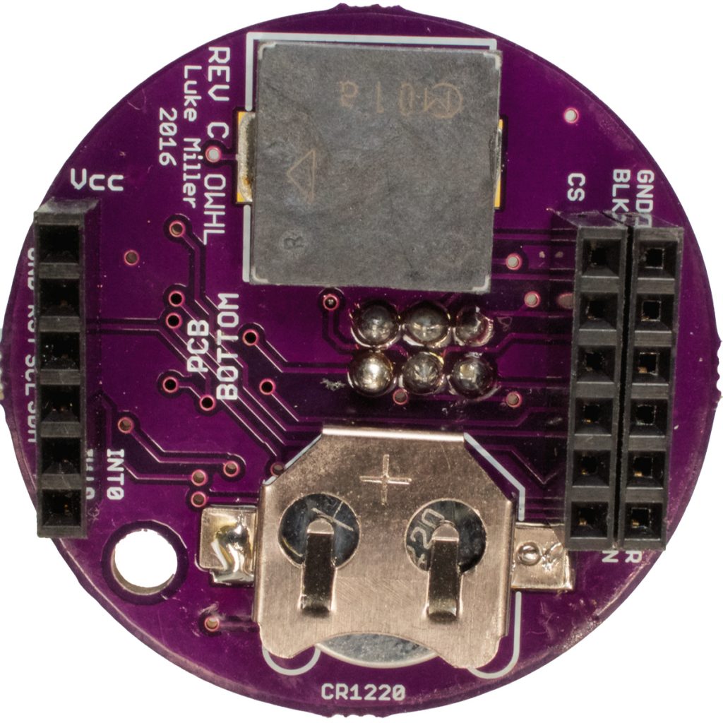
After the board has cooled, turn the board upside down (Figure 3). On the bottom side of the board, place a small layer of solder using a soldering iron on the pad in the middle of the battery holder footprint labeled CR1220.
Place the CR1220 battery holder (CPU PCB parts list U$2) on the footprint on the bottom surface of the CPU board. Make sure the open side of the holder faces the outer edge of the circuit board, following the outline pattern on the circuit board. Solder the tabs on each side of the battery holder in place using a soldering iron.
Place the piezo buzzer (CPU PCB parts list PIEZO) on the bottom surface of the circuit board. The solder pads on the buzzer match up with the footprint on the board in two orientations, either orientation can be used. Solder in place using a soldering iron.
Insert the 2×3 header (CPU PCB parts list J1) from the top side of the CPU circuit board. Solder the pins on the bottom side of the board using a soldering iron.
Insert 1×6 female wire-wrap headers (CPU PCB parts list SPI_HDR, I2C_HDR, FTDI_HDR) from the bottom side of the CPU board. Solder the pins on the top side of the board using a soldering iron. Do not clip the long pins of the headers.
Install a CR1220 battery into the holder, with the positive surface oriented upward, matching the + sign marked on the battery holder.
Figure 3. Left: bottom surface of a bare CPU circuit board. Right: bottom surface of the CPU board with all parts installed.
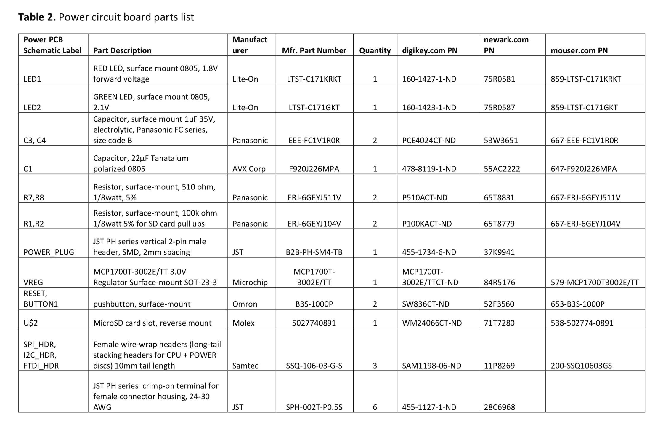
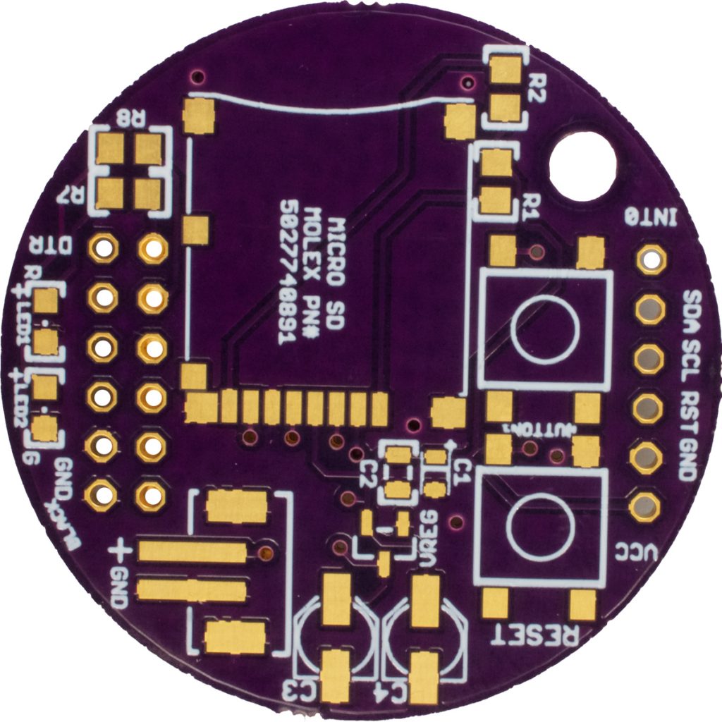
2.3 Power Board Assembly Steps
Use a solder paste stencil, or solder paste syringe, to apply solder paste to the solder pads on the bottom surface of the Power circuit board. Do not place solder on the through-hole pads, as these will be soldered separately.
Place 1 μF capacitors (Power PCB parts list C3, C4) on positions C3, C4. Refer to the outline on the circuit board for proper orientation. The plastic base of the capacitor has slanted corners on one end, and these should match the pattern on the board. The black stripe on the top of the metal can of the capacitor should be closest to the outer edge of the circuit board.
Place the JST PH-series battery connector (Power PCB parts list POWER_PLUG) on its pattern. Follow the orientation of the footprint on the board. Current versions of the Power board also include a pair of through-hole terminals labeled +BAT and GND that could be used to attach wires from another battery connector type instead of the JST connector.
Place the voltage regulator (Power PCB parts list VREG) on its footprint.
Place 22 μF tantalum capacitor (Power PCB parts list C1) on footprint C1. The footprint for C1 has a white stripe at one end, and a + sign near that same end. The capacitor should have a white stripe on one end. Orient the stripe on the capacitor towards the + sign, so that it is closest to the microSD footprint.
Place the red LED (Power PCB parts list LED1) on footprint LED1. The footprint has a + sign marking the positive pad. When viewing the LED from above (normally requiring a magnifying lens), a green dot marks the ground pin of the LED. Place the LED so that its ground pin is on the pad opposite the pad marked with the + sign.
Place the green LED (Power PCB parts list LED2) on footprint LED2. As with the red LED, when viewing the LED from above, a green dot will mark the ground pin. The circuit board footprint has a + sign near the positive pin of the footprint. Place the LED so that the green dot is on the pad opposite the pad marked with a + sign.
Place 510 ohm resistors (Power PCB parts list R7, R8) on footprints R7, R8 (orientation does not matter).
Place the micro SD card holder (Power PCB parts list U$2) on its footprint.
Place the pushbuttons (also known as tactile switches, Power PCB parts list RESET, BUTTON1). They will match up with the circuit board footprint in two orientations and will work in either orientation.
Place 100k ohm resistors (Power PCB parts list R1, R2) on footprints R1, R2.
Solder the surface mount components using a reflow solder oven or hot air reflow station.
Figure 4. Left: The bottom surface of a bare power circuit board.
Right: The bottom surface of a power circuit board with all components installed.
2.4 Power Circuit Board Assembly Continued
Insert three 1×6 female wire-wrap headers (Power PCB parts list SPI_HDR, I2C_HDR, FTDI_HDR) from the bottom surface of the circuit board. Solder the pins on the top surface using a soldering iron. Leave the pins long so they mate with the female headers of the CPU circuit board.
2.5 MS5803 Sensor Board Build
The MS5803-14BA pressure sensor (MS5803 PCB parts list U1) comes pre-soldered, so no additional solder is needed to attach the sensor to the circuit board.
Apply liquid or paste flux to the 8 pads of the MS5803 footprint on the top surface of the circuit board, and place the MS5803-14 chip on the footprint.
Alignment: The MS5803-14 when viewed from above, has a blue dot in one corner of the chip (Figure 6 Center). This blue dot should be matched to the dot next to the MS5803 label on the circuit board. Additionally, the MS5803-14, when viewed from the bottom, has one longer solder pad. Match this longer solder pad to the one longer pad on the circuit board footprint (Figure 6 Left).
Using a reflow oven or hot air reflow station, solder the MS5803-14 to the circuit board.
After the MS5803-14 chip is attached, turn the circuit board over. Apply solder paste to the pads of position C5 labeled on the bottom surface of the board (Figure 6 Right). Place the 0.1 μF capacitor (MS5803 PCB parts list C5) in position C5.
Solder C5 using a hot air reflow tool or soldering iron.
Insert three 1×6 female headers (MS5803 PCB parts list SPI_HDR, I2C_HDR, FTDI_HDR) in the three 1×6 header positions on the circuit board. Insert the headers from the bottom side of the circuit board, so that their tails will be soldered on the top surface of the board. Solder using a soldering iron. Trim the tails on the top surface of the circuit board after soldering to avoid interference when the MS5803-14 is mounted to the bulkhead.
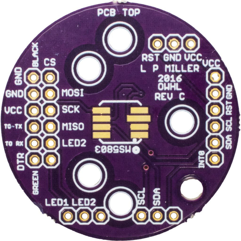
Figure 6a: The upper surface of a bare MS5803 sensor circuit board.
Fig. 6b: Top surface of the MS5803 board with MS5803-14BA sensor and 1x6 header pins installed.
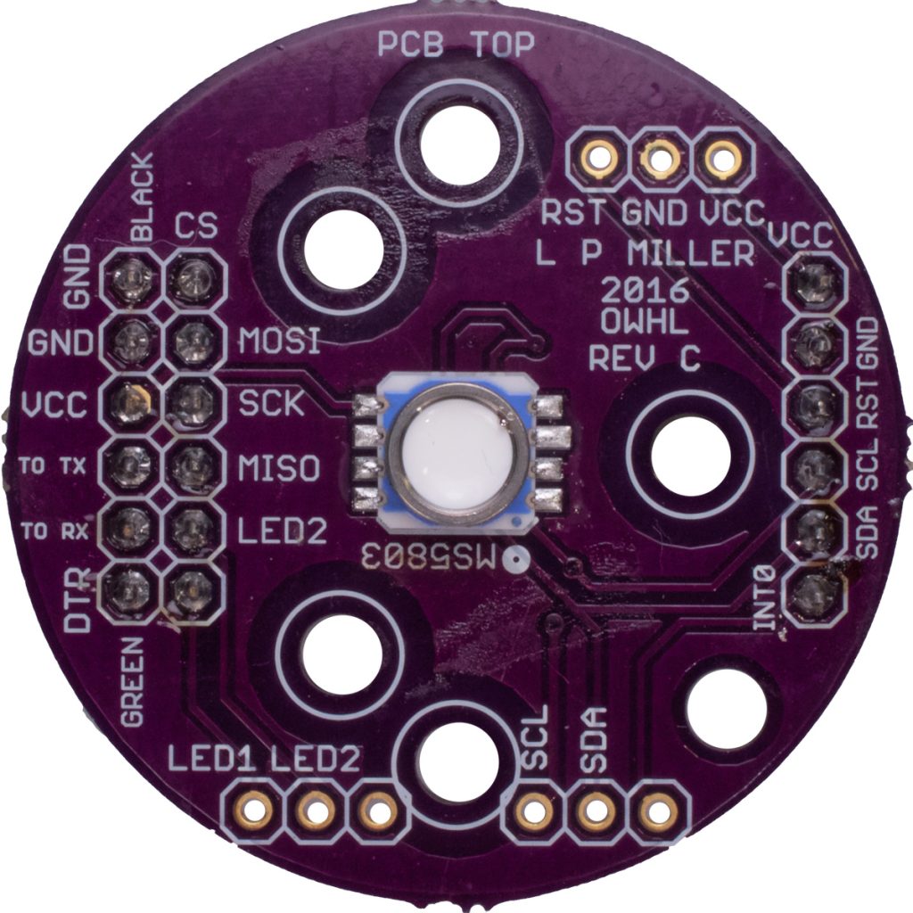
Fig. 6c: Bottom surface of the MS5803 board with capacitor C5 and 1x6 headers installed.