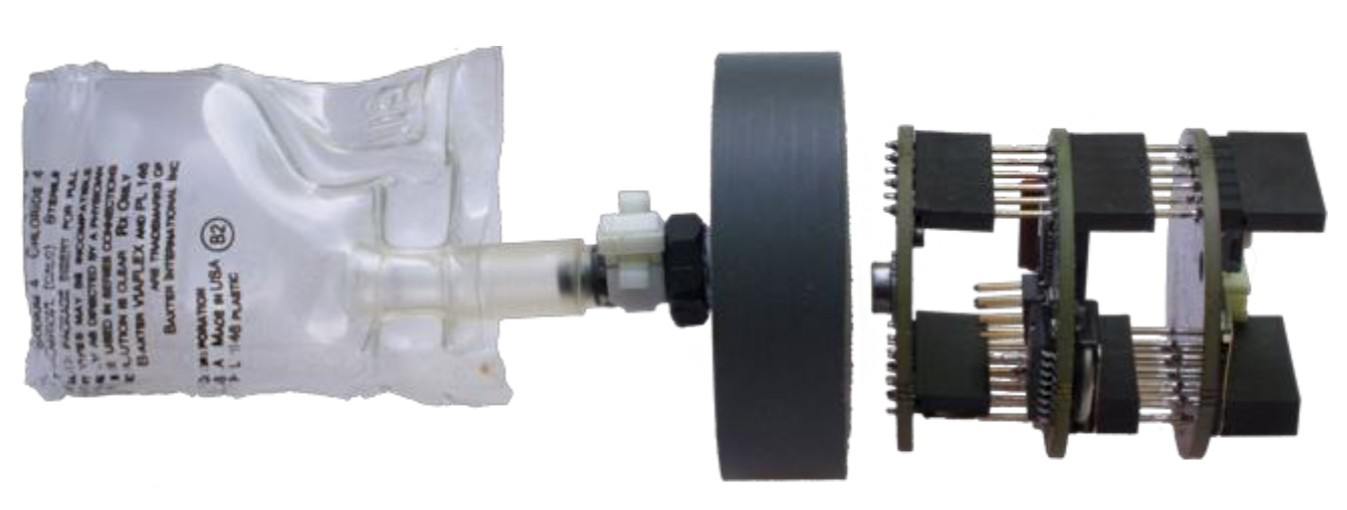
The bulkhead (Figure 20) is the interface between the Measurement Specialties MS5803-14BA pressure sensor (protected on the inside of housing) and an oil-filled reservoir (attached to the exposed outside of housing). It is most easily made by using a 2” (50 mm) hole saw on a PVC sheet to make a circular blank. The PVC blank is then drilled and threaded to make the bulkhead fitting for the logger.
Please note:
This part can also be produced using more highly specialized machine shop tools to produce a more uniform and cleaner part.
Figure 20: Bulkhead with oil reservoir and electronics.
2. Our original design for the bulkhead included a small step in the piece that allows the electronics to sit flush with the union fitting. Some photos may show this detail, however it is not required and frankly just makes more work.
Simple Build Instructions for Making the Bulkhead
This method to make the bulkhead fitting produces a less uniform and rougher part, but requires no highly specialized tools or training to produce. A 2” (5.08 cm) hole saw is used to plunge cut a flat 3/4” (1.9 cm) thickness PVC sheet stock. This method works best with a shop drill press
Tools Needed:
Drill Press (preferred) or Powered Hand Drill
Center Punch (optional)
Hole Saw Arbor with 1/4” bit (6.35 mm)
2” Hole Saw (50mm)
‘R’ drill bit (‘R’ bit size = 0.3390″ or 8.61 mm)
11/32″ is the closest fractional bit (0.3437″ or 8.73 mm).
Cutting the Bulkhead Blank Using a Drill Press (or Powered Hand Drill)
Measure out the placement for the bulkhead(s) on the PVC sheet.
While not required, using a center punch to mark the starting point for the drill bit keeps the bit from wandering and produces more uniform results
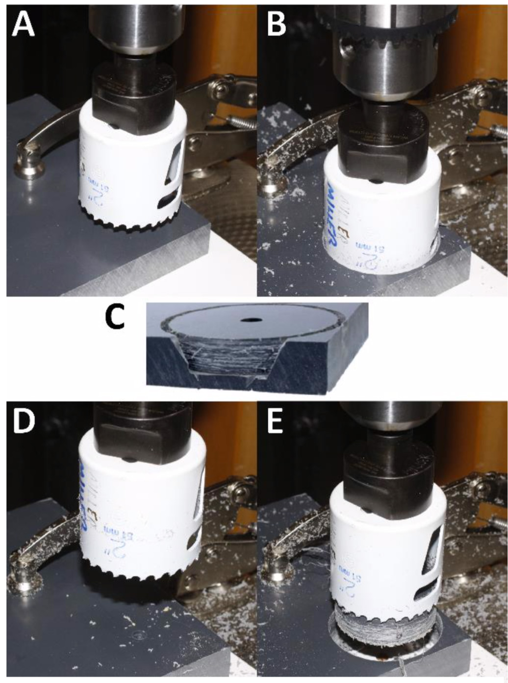
Secure the sheet material with a clamp or vise to ensure repeatable placement of drill bit (Figure 21A). Do not attempt to hand-hold the sheet while drilling with a hole saw.
Using a 2” (50.8 mm) hole saw on an arbor with a 0.25” (6.35 mm) bit:
Carefully cut a circular blank (the bulkhead) out of the PVC sheet.
Not drilling completely through the sheet in one pass gave better results.
Drill to 90% of the thickness (Figure 21B & C)
Flip PVC sheet over
Use the exiting center hole to align the arbor bit (Figure 21D)
Cut remaining material (Figure 21E)
Remove PVC blank from the hole saw
Remove bulkhead from the hole saw
The newly cut blank needs to be pried out of the hole saw each time
A small flat-blade screwdriver works well
Figure 21. A) Clamp the PVC sheet securely in a drill press. B) Drill partway through the PVC sheet using a 2” (51mm) diameter hole saw with a 1⁄4” center drill. C) A partially drilled PVC sheet. D) Turn the PVC sheet over, and center the hole saw using the center hole from the previous drilling step. E) Finish drilling through the PVC sheet, and remove the bulkhead, using a small flatblade screwdriver to pry it loose if it becomes stuck in the hole saw.
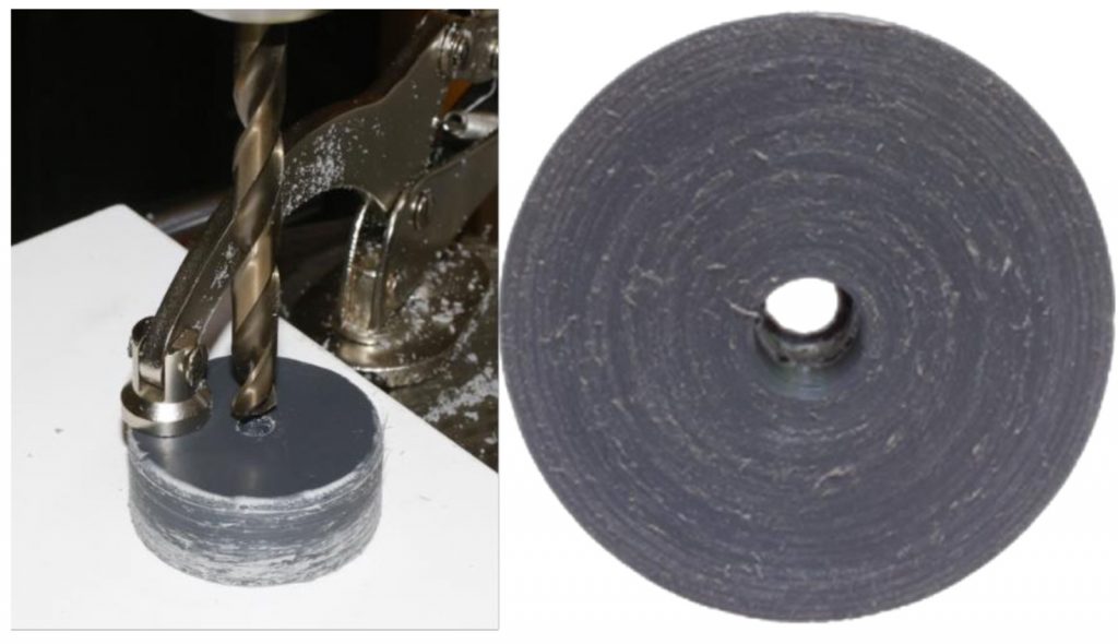
Figure 22: Left: Use a size R drill bit to partially drill the existing center hole in the bulkhead. Right: The drilled hole in the bulkhead for the barbed fitting. This hole will have threads cut into it using a tap.
Drilling the Hole for the 1/8” NPT Fitting
Next step is to drill out a portion of the existing 1/4” (0.635 cm) hole in the blank for the 1/8” NPT thread barbed fitting on the “outside” of the bulkhead. Again, with a drill press or hand drill:
Use the ‘R’ drill bit (diameter 8.611 mm, 0.339”) to make a pilot hole for the 1/8” NPT fitting
Drill ~ 1/2” to 5/8” (1.27 to 1.5875 cm) depth into one side of the bulkhead (Figure 22)
Continue to “Tapping the hole for the 1/8” NPT fitting”.
Tapping the Hole for the 1/8″ NPT Fitting
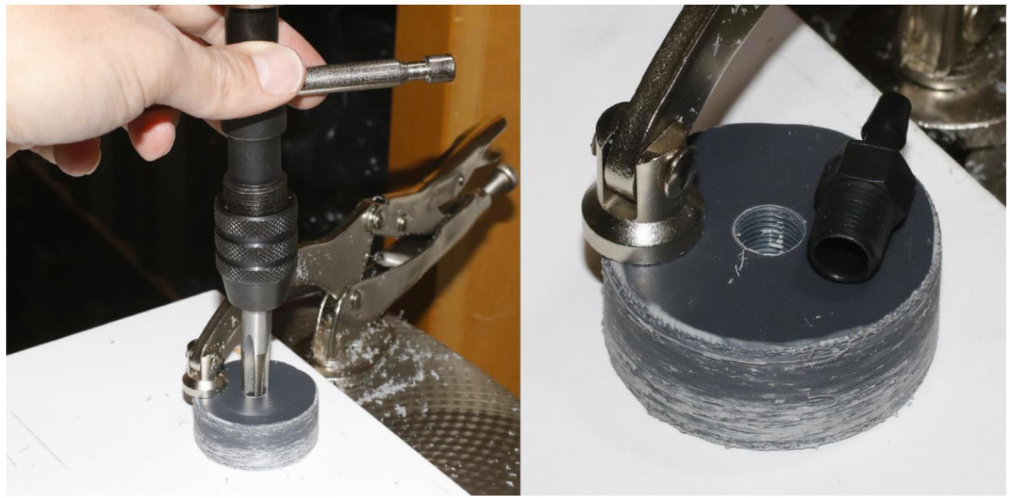
The larger hole needs to have threads cut into it (tapped) to accept the fitting that will attach the oil reservoir (Figure 22). Tapping plastic can be tricky as it is easy to either misalign the tap and have it enter at an angle, or the new threads can break if too much force is exerted. Make sure that the tap is started in the hole as close to vertical as possible. Hand starting the tap is acceptable if done cautiously, however, starting the tap with the aid of a jig, a drill press or with a specialized tapping tool found in many machine shops is preferable. Only cut a few threads at a time, backing out to clear the cut material and then repeating. Never force the tap, especially as you reach the bottom of the hole, as it can easily break the newly cut threads. Using a plastics safe cutting lubricant can also help.
Tools Needed:
Hand tap wrench 1/8” NPT tap (tapered pipe thread) Vise (or equivalent)
Materials needed:
PVC Bulkhead
Plastics safe cutting lubricant (optional)
Steps
Gently secure the bulkhead in a vise or equivalent, as cutting threads is hard to do by hand-holding the material (Figure 23).
Carefully begin by aligning the tap with the axis of the hole.
If using a cutting lubricant, apply a few drops to the tap first
Using gentle pressure, begin by turning the tap in a clockwise direction.
Make slow clockwise turns until you feel the tap beginning to engage the PVC and cut new threads.
After cutting the first few threads, gently reverse direction and clear out the cut material.
Carefully realign the tap and gently turn clockwise again to re-engage threads at the previous endpoint.
Continue cutting new threads a few at a time and then backing out to clear cut material until you reach the desired depth of ~ 3/8” (0.9525 cm) of the threaded hole.
Use cutting lubricant as needed
Figure 23: Left: Align the tap in the hole, ensuring that the tap stands perpendicular to the bulkhead. Slowly turn the tap in clockwise a few turns at a time by hand, and back the tap out counterclockwise every few turns to clear out the cut material. Right: The tapped threads are visible center hole, next to the barbed fitting.
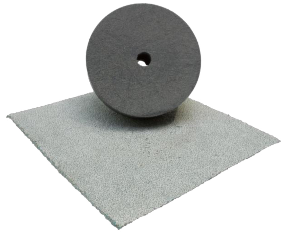
Sanding the bulkhead surface for gluing the sensor board to it
The smooth PVC on the sensor side of the bulkhead needs to be roughened up to give better adherence for the glue (Table 7, Item 31).
Use some rough grit sandpaper to roughen the sensor-side surface of the bulkhead (Figure 24).
Gluing the MS5803 Circuit Board to the Bulkhead
Although the MS5803 circuit board has a series of holes that can be used for mounting the board against the bulkhead, we have found that adhesive marine sealant is sufficient for adhering and waterproofing the interface between the circuit board and the PVC bulkhead.
Figure 24: Roughen the interior surface of the bulkhead where the pressure sensor circuit board will be glued.
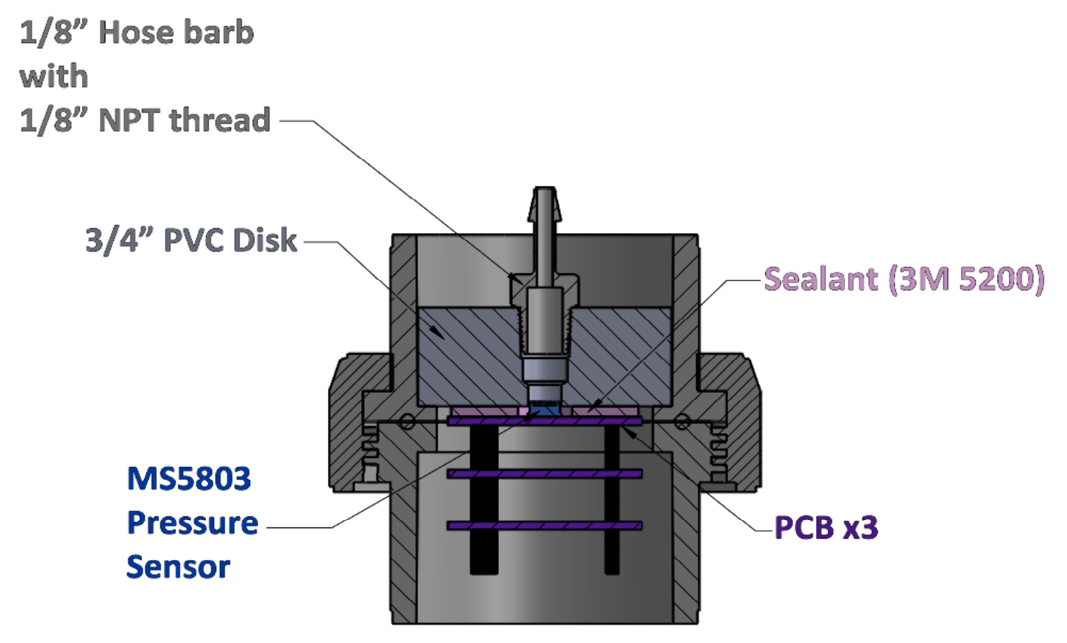
Figure 25: Cross-section view of the union fitting. The OWHL pressure sensor board is glued to the bottom of the 3⁄4” PVC bulkhead fitting with 3M 5200 adhesive, and the bulkhead fitting is glued into the upper half of the union fitting.
Tools needed:
Spring or screw-clamps
Materials needed:
Assembled MS5803 circuit board
PVC bulkhead (from the previous section)
3M Marine Adhesive Sealant Fast Cure 5200
Steps
Apply a thin layer of 3M 5200 sealant to the PVC bulkhead on the side with the smaller hole
Apply a thin layer of 3M 5200 sealant to the top surface of the MS5803 circuit board. (Figure 26)
Figure 26: Left: apply adhesive to the surface of the bulkhead fitting on the side with the smaller hole. Right: apply adhesive to the top surface of the MS5803 circuit board, taking care to avoid getting adhesive on the white membrane of the sensor itself.
Press the adhesive-covered surfaces of the bulkhead and circuit board together. Use a gentle twisting motion to try to eliminate air pockets and spread the adhesive evenly. Ensure that the adhesive does not get on to the white membrane of the MS5803 pressure sensor as it is inserted into the hole of the bulkhead, but do make sure to get an even layer of adhesive between the inner surface of the hole in the PVC bulkhead and the stainless steel ring of the MS5803-14 sensor (Figure 27).
Figure 27: Left: roughened PVC bulkhead ready to receive adhesive. Center: MS5803 circuit board adhered to the bulkhead. Right: A view into the larger hole of the PVC bulkhead after mounting the MS5803 circuit board. The white membrane of the MS5803-14BA pressure sensor is visible in the center, and a layer of white adhesive has filled the space between the stainless steel ring of the pressure sensor and the PVC bulkhead hole.
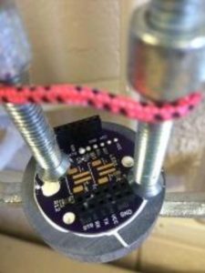
Use a pair of spring clamps or c-clamps to apply light pressure to the two pieces and hold them together while the adhesive cures for 24 h (Figure 28).
Figure 28: A pair of c-clamps maintain light pressure on the MS5803 circuit board and the PVC bulkhead while the adhesive cures.
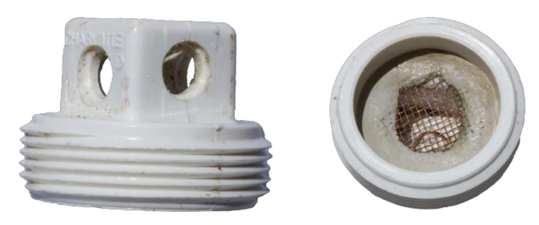
Modifying the Cleanout Plug
We need to drill out the end of the cleanout plug to allow for an unimpeded flow of water around the oil reservoir. These holes also provide an anchor point for standard wire-ties. A copper mesh screen is glued in place to reduce fouling and prevent small fish from making it a home (Figure 29).
Tools Needed:
Snips or scissors
1/4” to 1/2” Step bit (or equivalent) to drill plastic plug
Vise (or equivalent)
Materials needed:
Copper Mesh 1-1/2 in. PVC DWV MIPT
Cleanout Plug (Table 4 Item 5)
5-minute epoxy or epoxy putty
Steps:
Cut a 2.5 cm x 2.5 cm (1” x 1”) square of copper mesh (Table 4 Item 9)
Drill a 3/8” hole on each side of the square end
On the inside of cleanout plug:
Epoxy in a 1” x 1” piece of copper wire mesh to prevent fouling and fish entry
Figure 29: Views of the modified cleanout plug. The image on the right shows the copper mesh screen epoxied into place inside the plug.
Making the Oil Reservoir
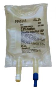
The Measurement Specialties MS5803-14BA pressure sensor is not rated for continuous saltwater use and given its small size, can be easily fouled. To mitigate this, our design isolates the pressure sensor port from direct seawater contact, using an oil-filled bladder as an intermediate connection between the outside seawater and the surface of the pressure sensor. The bladder is made by modifying a small 25mL intravenous fluids (IV) bag once used for saline (Figure 30). * Note: any IV bag size can be used
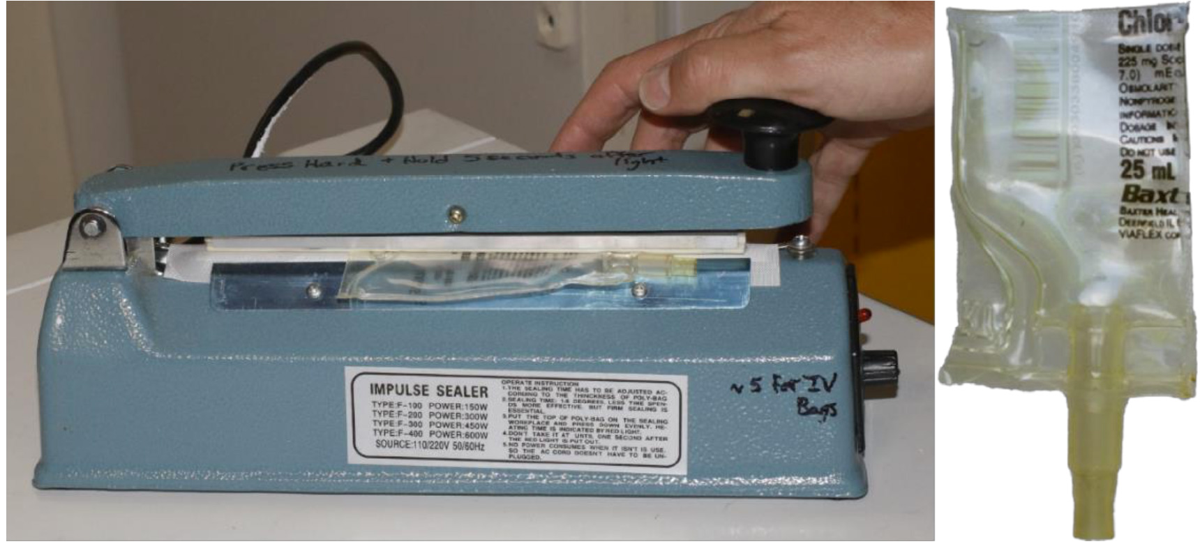
A commercial “Impulse Heat Sealer” like those used to package small retail products was used to carefully fuse the IV bag in several key places (Figure 31). Since the IV bag has two ports, we can get 2 oil reservoirs from each IV bag.
Tools Needed:
Impulse Heat Sealer
Utility Knife or Scissors
3/16” Drill Bit or equivalent (4.5 mm, #13 or 0.1875”)
Materials needed:
25 mL Saline IV bags
Items needed to test bag:
Aquarium airline tubing (needs to fit directly onto IV bag nipple or use with an adapter)
Cup (filled with water)
Figure 30: Saline IV bag used to produce the oil reservoir.
Reduce the size of the IV bag and drain out the saline solution
With scissors, cut the top off the IV bag first to drain it
Our finished oil bags have an approximate length of 6 cm as measured from the bottom of the bag (tube end)
Drain out the Saline
Remove the protective caps from both tubes Using a 3/16” (0.476 cm) drill bit:
Cut out the internal seals in both the tubes With scissors, cut the IV bag in half, lengthwise
Let the bag dry before the next step
The bags need to be reasonably dry inside as any saline left in the bag may prevent the heat sealer from working well
Figure 31: Left: Using a heat sealer to seal the cut edge of an IV bag. Right: A modified IV bag, after re-sealing the trimmed edges of the cut-down bag.
Using the Impulse sealer
To seal the bag edges:
Set the dial on the impulse sealer for the max of 8 seconds.
Use the impulse sealer to heat each side of the bag and fuse the melting plastic
Heat the bag approximately 2-3 times on each side of the bag.
Push and hold the sealer for the 8 seconds, three times in quick succession
Quickly flip the bag over and use the sealer an additional 2 to 4 more times (depending on how hot your sealer is)
For the last 2-4 presses, just ever so slightly move the bag from side to side to broaden the contact patch.
At the end of the last 8 seconds press, push down hard on the impulse sealer bar, holding this for an additional 10-15 seconds with the bar closed
Let the newly melted seam cool slightly with the bar pressure on it before removing it from the sealer.
Test the oil reservoir for any leaking
To test the new edge seals of the oil reservoir bags:
Fit an aquarium airline tube to the bag nipple
Using a container of water, gently blow on the airline tube and look for any air leaking from the reservoir bag.
For any leaks found:
Repeat the above steps as necessary directly on the leak point
Sometimes the leak is right at the corner of the two intersecting heat points
In this case, reseal at 45 degrees to the corner, making a small sealed triangle point over the leak.