Tools Needed:
- PVC Saw (or equivalent to cut the PVC pipe to length)
- Crescent Wrench (or equivalent for the 1/8” NPT fitting)
- Pliers (Needle Nose Pliers recommended)
- A syringe with large bore tip
- A syringe with fine bore tip
Materials needed (pipe sizes are given as nominal diameters):
- 1-1/2 in. PVC Socket Cap (Table 4 Item 2)
- 1-1/2 in. PVC DWV Plain End Pipe (Table 4 Item 1)
- 1-1/2 in. PVC Slip x Slip Union (Table 4 Item 3)
- 1-1/2 in. PVC DWV Hub x FIPT Female Adapter (Table 4 Item 4)
- 1-1/2 in. PVC DWV MIPT Cleanout Plug (Table 4 Item 5)
- 1-1/2 in. PVC S x S Coupling (Optional) (Table 4, Item 6)
- 1-1/2 in. Clear PVC Pipe (Optional) (Table 4, Item 7)
- PVC Primer (Table 4 Item 10)
- PVC Solvent Cement (Table 4 Item 10)
- Mineral Oil
Cut List to Make *One* OWHL Housing
- 1 x 4” piece of 1-1/2” DWV plain end pipe
- 1 x 10” piece of 1-1/2” DWV plain end pipe
(** if using optional clear section add the following:)
- 1 x 4” piece of 1-1/2” Clear PVC tube
- 1 x 6” piece of 1-1/2” DWV plain end pipe
Assembly of the Housing Parts in Order
- End cap
- 10” length of 1-1/2” PVC Pipe (6” length if using optional clear section)
- S x S Coupling (Optional)
- 4” piece of 1-1/2” Clear PVC tube (Optional)
- Bulkhead fitting
- Union – Threaded half
- Union O-ring (carefully set aside the union fitting O-ring for final assembly)
- Union – Flange half
- Union – Locking nut
- 4” length of 1-1/2” PVC pipe
- Hub x FIPT Female Adapter
- MIPT Cleanout Plug
For all PVC solvent cement welds (gluing parts together)
- All pieces to be glued should be reasonably clean and debris free
- All glue joints should be primed with Purple PVC Primer or equivalent
- Both pieces to be glued should get a light coating of PVC solvent cement at the mating points using the dauber brush provided in the cap of the PVC cement
- Pieces should then be pushed together tightly and a slight twist given to spread the glue
- Hold the pieces together for at least 30 to 60 seconds after gluing
- The heat from the solvent cement weld reaction can cause pieces to back out from expansion.
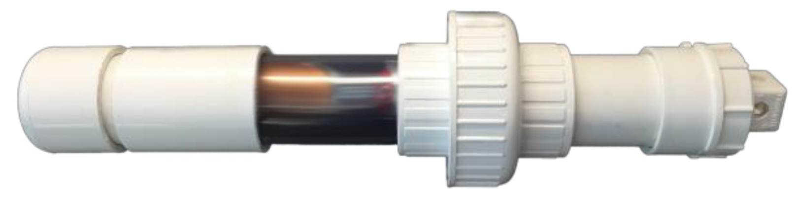
- Begin by gluing the bulkhead fitting to the threaded half of the union fitting
- Make sure that the 1/8” NPT threaded fitting side is facing out
- Coat the area that the bulkhead will sit in the union fitting with PVC solvent cement
- Insert the bulkhead and twist slightly to spread the solvent cement
- Use a paper towel to clean up any excess cement in the union fitting
- The 4” long piece of pipe will need to be glued in above this point
- Any dried PVC cement may prevent it from seating properly
- Glue the End cap on to the 10” length of pipe
- (6” length if using the clear section)
- Glue the 10” length of pipe into the threaded end of the Union fitting above the bulkhead
- (If using the clear pipe section, glue on the coupling and then clear piece of PVC)
1. Oil Reservoir Installation
Install the oil reservoir components from the previous section.
- Install the 1/8” NPT fitting using 3 wraps of Teflon thread tape or equivalent
- Use a crescent wrench or equivalent to tighten the fitting
- Do not over-tighten
- Use a crescent wrench or equivalent to tighten the fitting
- Install the 4” length of pipe to protect the oil reservoir
- Install the FIPT Female Adapter
2. Filling the Oil Reservoir
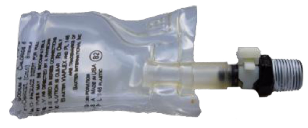
It is now easiest to fill the oil reservoir with mineral oil before screwing on the cleanout plug. The end goal is a partially oil-filled bag attached to the barbed nipple fitting with no air bubbles in it (or only a few tiny bubbles less than 1 mm in diameter). The bag should only be half-filled with mineral oil to avoid introducing extra pressure on the sensor due to the elasticity of a fully-filled IV bag.
- Use a syringe with a large-bore end to fill the oil reservoir with mineral oil
- Add mineral oil to the IV bag
- Start by pressing the bag flat to push out most of the air
- Hold the bag upright with the tube fitting up
- Fill the bag about half full of oil
- There may be some air bubbles remaining in the bag
- Gently tapping the bag may help get the larger bubbles out
- Squeezing carefully from the bottom of the bag may help force air bubble out the top of the tube fitting
- Use a fine-gauge syringe to suck out any remaining smaller air bubbles
- There may be some air bubbles remaining in the bag
- Sit the bulkhead with the barbed fitting upright. Add mineral oil to the barbed pipe fitting until a small meniscus of oil forms at the top of the fitting
- Tap the fitting and bulkhead repeatedly to make sure any bubbles trapped in the bottom of the barbed fitting near the sensor port rise to the top and escape
- A long syringe needle can be used to inject oil deep in the barbed fitting and agitate the fluid to force air bubbles up out of the barbed fitting
- Install the oil reservoir bag on to the 1/8” NPT fitting barbed nipple. Both parts should be brimming with oil, and a bit of oil will escape as you press them together, hopefully without introducing any large air bubbles
- Install the clamp on to the oil reservoir tube over the barbed fitting
- About halfway down the tube and between the barbs gives the tightest seal
- Squeeze clamp with pliers carefully to seal
- Over-tightening the clamp can lead to it breaking
- Add mineral oil to the IV bag
Once the bag is mounted on the barbed fitting, test the bag integrity by pressing down with the heel of your hand on the assembled oil-filled bag against a hard surface like a tabletop or lab workbench. The oil reservoir should not pop or leak.